Magnetic Particle Testing (MT)
Magnetic Particle Testing (MT)
While indications can be observed from subsurface discontinuities very near the surface, they are very difficult to interpret, and often require testing by other methods.
Other NDE techniques are usually required for subsurface discontinuity detection and interpretation.
However, surface discontinuities present in a magnetized part will cause the applied magnetic field to create “poles” of opposite sign on either side of the discontinuity, creating a very attractive force for iron particles.
If iron particles, which are “magnetic particles” since they can become magnetized, are spnnkled on this surface, they will be held in place by this attractive field to produce an accumulation of iron particles and a visual indication of the discontinuity.
While several different types of magnetic particle tests exist, they all rely on this same general principle.
Therefore, all of these tests will be conducted by creating a magnetic field in a part and applying the iron particles onto the test surface.
To understand magnetic particle testing, it is necessary to have some basic knowledge of magnetism; therefore, it is appropriate to describe some of its important characteristics.
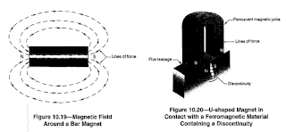
To begin this discussion, refer to Figure 10.19 which shows a diagram of the magnetic field associated with a bar magnet.
Looking at this diagram, there are several principles of magnetism which are demonstrated.
First there are magnetic lines of force, or magnetic flux lines, which tend to travel from one end (or pole) of the magnet to the opposite end (pole).
These poles are designated as the north and south poles.
The magnetic flux lines form continuous loops which travel from one pole to the other in a single direction.
These lines always remain virtually parallel to one another and will never cross each other.
Finally, the force of these flux lines (and therefore the intensity of the resulting magnetic field) is greatest when they are totally contained within a ferrous or magnetic material.
Although they will travel across some air gap, their intensity is reduced significantly as the length of the air gap is increased.
Figure 10.20 shows a configuration in which a bar magnet similar to the one in Figure 10.19 has been bent into a U-shape and is in contact with a magnetic material containing a discontinuity.
There are still magnetic lines of force traveling in continuous loops from one pole to the other.
However, now the piece of steel has been placed across the ends of the magnet to provide a continuous magnetic path for the lines of force.
While there is some flux leakage present at the slight air gaps between the ends of the magnet and the piece of steel, the magnetic field remains relatively strong because of the continuity of the magnetic path.
Now consider the discontinuity which is present in the steel bar; in the vicinity of that discontinuity, there are magnetic poles of opposite sign created on either side of the air gap present at the discontinuity.
These poles of opposite sign have a strong attractive force between them, and if the area is sprinkled with iron particles, those particles will be attracted and held in place at the discontinuity.
Therefore, to perform magnetic particle testing, there must be some means of generating a magnetic field in the test piece.
Once the part has been magnetized, iron particles are sprinkled on the surface.
If discontinuities are present, these particles will be attracted and held in place to provide a visual indication.
The examples discussed so far have depicted permanent magnets.
However, use of permanent magnets for magnetic particle testing is done infrequently; most magnetic particle testing uses electromagnetic equipment.
An electromagnet relies on the principle that there is a magnetic field associated with any electrical conductor, as shown in Figure 10.21.
When electricity is passed through a conductor, the magnetic field which is developed is oriented perpendicular to the direction of the electricity.
There are two general types of magnetic fields which are created in test objects using electromagnetism: longitudinal and circular, The types refer to the direction of the magnetic field which is generated in the part.
When the magnetic field is oriented along the axis of the part, it is referred to as longitudinal magnetism.
Similarly, when the direction of the magnetic field is perpendicular to the axis of the part, it is called circular magnetism.
There are several ways in which these two types of magnetism can be created in a test part.
Figure 10.22 illustrates a typical longitudinal magnetic field created by surrounding the part with a coiled electrical conductor.
When using a stationary magnetic particle testing machine, this would be referred to as a “coil shot.”
When electricity passes through this conductor, a magnetic field is created as shown.
With this magnetic field, those flaws lying perpendicular to the lines of force will be easily revealed.
Those lying at 45” to the magnetic field will also be shown, but if a flaw lies essentially parallel to the induced magnetic field, it will not be revealed.
The other type of magnetic field is referred to as circular magnetism.
To create this type of field, the part to be tested becomes the electric conductor so that the induced magnetic field tends to surround the part perpendicular to its longitudinal axis.
On a stationary testing machine, this would be called a “head shot.”
This is illustrated in Figure 10.23. With circular magnetism, longitudinal flaws will be revealed while those lying transverse will not.
Those at approximately 45” will also be shown. An important aspect of the circular magnetic field is that the magnetism is totally contained within the ferromagnetic material whereas the longitudinal magnetic field is induced in the part by the electric conductor which surrounds it.
For this reason, the circular magnetic field is generally considered to be somewhat more powerful, making circular magnetism more sensitive for a given amount of electric current.
When trying to determine the orientation of discontinuities which are likely to form indications, start by determining the direction of the electric current, then consider the direction of the induced magnetic field, and then determine the discontinuity orientation which will give optimum sensitivity.
Both types of magnetic fields can also be generated in a part using portable equipment.
A longitudinal field results when the “yoke” method is used
A yoke unit is an electromagnet, and is made by winding a coil around a soft magnetic material core.
Current flowing through the coil induces a magnetic field which flows across the test object between the ends of the yoke.
To produce a circular magnetic field with a portable unit, the “prod” technique is used.
Use of this method for weld testing is illustrated
Either alternating (AC) or direct current (DC) can be used to induce a magnetic field.
The magnetic field created by alternating current is strongest at the surface of the test object.
AC current will also provide greater particle mobility on the surface of the part allowing the particles to move about more freely which aids flaw detection, even when the surface of the part may be rough and irregular.
Direct current induces magnetic fields which have greater penetrating power and can be used to detect near-surface discontinuities.
However, these indications are very difficult to interpret.
A third type of electric current is referred to as half wave rectified AC and can be thought of as a combination of both AC and DC.
With this type of power usage, benefits of both types of current can be achieved.
It has been stated that magnetic particle testing is most sensitive to discontinuities perpendicular to the magnetic lines of flux and that discontinuities parallel to the lines of flux might not be detected at all.
At angles between these extremes a grey area exists.

In general, if the acute angle formed between the lines of flux and the long axis of the discontinuity is greater than 45”, the discontinuity will form an indication.
At angles less than 45” the discontinuity might not be detected.
Therefore, to provide complete evaluation of a part to locate flaws lying in all directions, it is necessary to apply the magnetic field in two directions 90” apart.
Applications of magnetic particle inspection include the evaluation of materials which are considered to be magnetic at the test temperature.
Such materials include steel, cast iron, some of the stainless steels (not the austenitic stainless steels), and nickel.
It cannot be used for testing aluminum, copper, or other materials which cannot be magnetized.
Properly applied, this test method can detect extremely fine surface discontinuities and will give “fuzzy” indications of larger, near-surface flaws.
Equipment used with this test method varies in size, portability and expense.
Lightweight AC yoke units are extremely portable and useful for inspection of objects too large to test otherwise.
Such objects might include buildings, bridges, tanks, vessels, or large weldments.
Less-portable equipment includes prods and coils.
Both typically require a special power source and may have limited mobility.
Stationary equipment usually includes mechanisms for both head and coil shots.
Parts inspected in stationary units might well be small with extremely high inspection rates or surprisingly large with correspondingly lower inspection rates.
The stationary units include demagnetization mechanisms.
The iron particles used are very small and are often dyed to provide a vivid color contrast with that of the test object.
Colors commonly available include gray, white, red, yellow, blue, and black.
These are called visible particles and are used under a strong visible light source.
Iron particles can also be obtained that are fluorescent under black light, and their test sensitivity is greater.
These magnetic particles are applied as a dry powder with a low velocity air stream or are flowed over the part as a suspension in inhibited water or light oil.
The dry method is called dry magnetic particle testing, and the oil or water suspension method is called wet magnetic particle testing.
Both methods are frequently used, but the wet fluorescent method has higher sensitivity and has become the method of choice for many field and shop applications, The advantages of MT are rapid testing speed and low cost.
The method can be made extremely portable and is very good for the detection of surface discontinuities.
Testing can be done through thin paint coatings.
The major limitation of magnetic particle testing is that it can only be used on materials that can be magnetized.
Other limitations are that most parts require demagnetization after testing and that very thick coatings may mask detrimental indications.
Demagnetization is usually done by the AC method and is done by either removing the part from the magnetizing field slowly or reducing the induced magnetizing current applied to the part to zero.
Electricity is required for most applications; this may limit portability.
Rough surfaces such as those seen on welds or castings can make evaluation more difficult.
Results of magnetic particle testing may be recorded by sketching, photographing or by placing adhesive cellophane tape over the indication and then transferring the tape to a clean piece of white paper.
This particular nondestructive test method is used primarily to discover surface discontinuities in ferromagnetic materials.
While indications can be observed from subsurface discontinuities very near the surface, they are very difficult to interpret, and often require testing by other methods.
Other NDE techniques are usually required for subsurface discontinuity detection and interpretation.
However, surface discontinuities present in a magnetized part will cause the applied magnetic field to create “poles” of opposite sign on either side of the discontinuity, creating a very attractive force for iron particles.
If iron particles, which are “magnetic particles” since they can become magnetized, are spnnkled on this surface, they will be held in place by this attractive field to produce an accumulation of iron particles and a visual indication of the discontinuity.
While several different types of magnetic particle tests exist, they all rely on this same general principle.
Therefore, all of these tests will be conducted by creating a magnetic field in a part and applying the iron particles onto the test surface.
To understand magnetic particle testing, it is necessary to have some basic knowledge of magnetism; therefore, it is appropriate to describe some of its important characteristics.
To begin this discussion, refer to Figure 10.19 which shows a diagram of the magnetic field associated with a bar magnet.
Looking at this diagram, there are several principles of magnetism which are demonstrated.
First there are magnetic lines of force, or magnetic flux lines, which tend to travel from one end (or pole) of the magnet to the opposite end (pole).
These poles are designated as the north and south poles.
The magnetic flux lines form continuous loops which travel from one pole to the other in a single direction.
These lines always remain virtually parallel to one another and will never cross each other.
Finally, the force of these flux lines (and therefore the intensity of the resulting magnetic field) is greatest when they are totally contained within a ferrous or magnetic material.
Although they will travel across some air gap, their intensity is reduced significantly as the length of the air gap is increased.
Figure 10.20 shows a configuration in which a bar magnet similar to the one in Figure 10.19 has been bent into a U-shape and is in contact with a magnetic material containing a discontinuity.
There are still magnetic lines of force traveling in continuous loops from one pole to the other.
However, now the piece of steel has been placed across the ends of the magnet to provide a continuous magnetic path for the lines of force.
While there is some flux leakage present at the slight air gaps between the ends of the magnet and the piece of steel, the magnetic field remains relatively strong because of the continuity of the magnetic path.
Now consider the discontinuity which is present in the steel bar; in the vicinity of that discontinuity, there are magnetic poles of opposite sign created on either side of the air gap present at the discontinuity.
These poles of opposite sign have a strong attractive force between them, and if the area is sprinkled with iron particles, those particles will be attracted and held in place at the discontinuity.
Therefore, to perform magnetic particle testing, there must be some means of generating a magnetic field in the test piece.
Once the part has been magnetized, iron particles are sprinkled on the surface.
If discontinuities are present, these particles will be attracted and held in place to provide a visual indication.
The examples discussed so far have depicted permanent magnets.
However, use of permanent magnets for magnetic particle testing is done infrequently; most magnetic particle testing uses electromagnetic equipment.
An electromagnet relies on the principle that there is a magnetic field associated with any electrical conductor, as shown in Figure 10.21.
When electricity is passed through a conductor, the magnetic field which is developed is oriented perpendicular to the direction of the electricity.
There are two general types of magnetic fields which are created in test objects using electromagnetism: longitudinal and circular, The types refer to the direction of the magnetic field which is generated in the part.
When the magnetic field is oriented along the axis of the part, it is referred to as longitudinal magnetism.
Similarly, when the direction of the magnetic field is perpendicular to the axis of the part, it is called circular magnetism.
There are several ways in which these two types of magnetism can be created in a test part.
Figure 10.22 illustrates a typical longitudinal magnetic field created by surrounding the part with a coiled electrical conductor.
When using a stationary magnetic particle testing machine, this would be referred to as a “coil shot.”
When electricity passes through this conductor, a magnetic field is created as shown.
With this magnetic field, those flaws lying perpendicular to the lines of force will be easily revealed.
Those lying at 45” to the magnetic field will also be shown, but if a flaw lies essentially parallel to the induced magnetic field, it will not be revealed.

The other type of magnetic field is referred to as circular magnetism.
To create this type of field, the part to be tested becomes the electric conductor so that the induced magnetic field tends to surround the part perpendicular to its longitudinal axis.
On a stationary testing machine, this would be called a “head shot.”
This is illustrated in Figure 10.23. With circular magnetism, longitudinal flaws will be revealed while those lying transverse will not.
Those at approximately 45” will also be shown. An important aspect of the circular magnetic field is that the magnetism is totally contained within the ferromagnetic material whereas the longitudinal magnetic field is induced in the part by the electric conductor which surrounds it.
For this reason, the circular magnetic field is generally considered to be somewhat more powerful, making circular magnetism more sensitive for a given amount of electric current.
When trying to determine the orientation of discontinuities which are likely to form indications, start by determining the direction of the electric current, then consider the direction of the induced magnetic field, and then determine the discontinuity orientation which will give optimum sensitivity.
Both types of magnetic fields can also be generated in a part using portable equipment.
A longitudinal field results when the “yoke” method is used
A yoke unit is an electromagnet, and is made by winding a coil around a soft magnetic material core.
Current flowing through the coil induces a magnetic field which flows across the test object between the ends of the yoke.
To produce a circular magnetic field with a portable unit, the “prod” technique is used.
Use of this method for weld testing is illustrated
Either alternating (AC) or direct current (DC) can be used to induce a magnetic field.
The magnetic field created by alternating current is strongest at the surface of the test object.
AC current will also provide greater particle mobility on the surface of the part allowing the particles to move about more freely which aids flaw detection, even when the surface of the part may be rough and irregular.
Direct current induces magnetic fields which have greater penetrating power and can be used to detect near-surface discontinuities.
However, these indications are very difficult to interpret.
A third type of electric current is referred to as half wave rectified AC and can be thought of as a combination of both AC and DC.
With this type of power usage, benefits of both types of current can be achieved.
It has been stated that magnetic particle testing is most sensitive to discontinuities perpendicular to the magnetic lines of flux and that discontinuities parallel to the lines of flux might not be detected at all.
At angles between these extremes a grey area exists.

In general, if the acute angle formed between the lines of flux and the long axis of the discontinuity is greater than 45”, the discontinuity will form an indication.
At angles less than 45” the discontinuity might not be detected.
Therefore, to provide complete evaluation of a part to locate flaws lying in all directions, it is necessary to apply the magnetic field in two directions 90” apart.
Applications of magnetic particle inspection include the evaluation of materials which are considered to be magnetic at the test temperature.
Such materials include steel, cast iron, some of the stainless steels (not the austenitic stainless steels), and nickel.
It cannot be used for testing aluminum, copper, or other materials which cannot be magnetized.
Properly applied, this test method can detect extremely fine surface discontinuities and will give “fuzzy” indications of larger, near-surface flaws.
Equipment used with this test method varies in size, portability and expense.
Lightweight AC yoke units are extremely portable and useful for inspection of objects too large to test otherwise.
Such objects might include buildings, bridges, tanks, vessels, or large weldments.
Less-portable equipment includes prods and coils.
Both typically require a special power source and may have limited mobility.
Stationary equipment usually includes mechanisms for both head and coil shots.
Parts inspected in stationary units might well be small with extremely high inspection rates or surprisingly large with correspondingly lower inspection rates.
The stationary units include demagnetization mechanisms.
The iron particles used are very small and are often dyed to provide a vivid color contrast with that of the test object.
Colors commonly available include gray, white, red, yellow, blue, and black.
These are called visible particles and are used under a strong visible light source.
Iron particles can also be obtained that are fluorescent under black light, and their test sensitivity is greater.
These magnetic particles are applied as a dry powder with a low velocity air stream or are flowed over the part as a suspension in inhibited water or light oil.
The dry method is called dry magnetic particle testing, and the oil or water suspension method is called wet magnetic particle testing.
Both methods are frequently used, but the wet fluorescent method has higher sensitivity and has become the method of choice for many field and shop applications, The advantages of MT are rapid testing speed and low cost.
The method can be made extremely portable and is very good for the detection of surface discontinuities.
Testing can be done through thin paint coatings.
The major limitation of magnetic particle testing is that it can only be used on materials that can be magnetized.
Other limitations are that most parts require demagnetization after testing and that very thick coatings may mask detrimental indications.
Demagnetization is usually done by the AC method and is done by either removing the part from the magnetizing field slowly or reducing the induced magnetizing current applied to the part to zero.
Electricity is required for most applications; this may limit portability.
Rough surfaces such as those seen on welds or castings can make evaluation more difficult.
Results of magnetic particle testing may be recorded by sketching, photographing or by placing adhesive cellophane tape over the indication and then transferring the tape to a clean piece of white paper.


Comments
Post a Comment